
Used on the end of a suction line to stop the fluids in the line emptying when the pump is turned off. This eliminates the need to prime your pump each time you start it.
| Model |
BSP thread |
Metric* |
| HFV25 |
1" |
25mm |
| HFV32 |
1 1/4" |
32mm |
| HFV40 |
1 1/2" |
40mm |
| HFV50 |
2" |
50mm |
| HFV63 |
2 1/2" |
63mm |
*Approx BSP Equivalent
Which size valve
Click here to help you choose
- Unrestricted flow
- Efficiency in excess of 95%. Many other types 35% - 60%.
- Valve opening and closing very responsive.
- Unique Product Design incorporates built in strainer.
- Operates via pressure differential.
- Operates at any angle or position.
- No poppet valve to wear.
- Easily serviced - if required.
- Blockage reduced due to low fluid velocity through slots.
- Strong Non-Corrosive Materials - Body; High Quality Glass Fibre Reinforced Nylon, Diaphragm; Nitrile Rubber, Spring; Stainless Steel. All components of this valve manufactured from materials approved for use with potable (drinkable) water.
- Maximum Recommended Working Pressure - 16 Bar (1600 kPa. 235 PSI) @ 20°C.
- When screwing metal products into valve, do not over tighten. All pipe work must be adequately supported.
Valve Operation
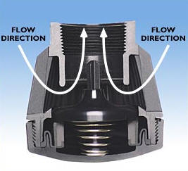 Cross section shows valve in fully open position
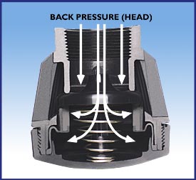 Cross section shows valve in fully closed position
When fluid is required in the direction of flow, the diaphragm opens allowing full flow. As the flow through the valve stops, the diaphragm closes preventing any return flow. The greater the back or head pressure, the better the diaphragm seals against the valve seat.